Analysis of a raw TCP/IP packet
In this chapter we are going to have a close look at some captured network packets and apply our knowledge from the previous parts of this series on them. You will see, that a lot of bits and bytes in packets will make much more sense.
Setup
To analyze TCP/IP packets, we are going to setup a small test environment. For this, we will use two machines, one as a (web-) server, the other one as client. You could also use only one system, however, then the source and destination IP address would be the same, making the analysis less intuitive.
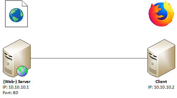 The webserver is serving a simple HTML website, which will be requests by a browser from the client. We will listen into this communication with the help of Wireshark, a widely-used network protocol analyzer. It doesn’t matter on which of those two systems you use Wireshark, as the communication between them is the same. For our convenience, we will hide non relevant packets with a display filter in Wireshark:
ip.addr == 10.10.10.1 && tcp.port == 80
Capturing packets
After accessing the webserver with our client’s browser, we observe all packets going from or to our server on port 80 with the help of Wireshark:
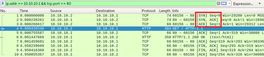
These are all the packets going back and forth between our client (10.10.10.2) requesting a webpage from our webserver (10.10.10.1). In the first three packets, we can see the previously described TCP three-way handshake ([SYN], [SYN, ACK], [ACK]) for the connection establishment.
In packet number 4, we can see a GET request from the client to the server, being acknowledged by the server in packet 5.
Packet 6 transmits the webpage data to the client, who acknowledges the receipt in packet 7.
Starting with packet 8, we can see a typical connection termination. After the webpage is transmitted from the server to the client, the server sends a [FIN, ACK] to signalize the termination of the connection from its side. The client sends a [FIN, ACK] to acknowledge the [FIN] of the server and send a [FIN] on its own. In packet 10 the server acknowledges the [FIN] of the client. The connection is now terminated.
The first packet in detail
We are going to look at the packet number 1 in more detail. For now we will ignore the first 14 bytes of the packet, but don’t worry, we’ll come back to them later.
IP segment
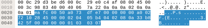
Wireshark shows us all the bits and bytes the packet consists of:
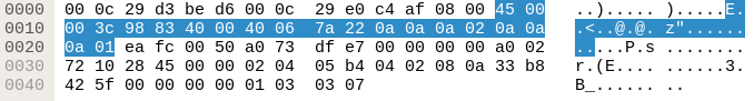
Highlighted in blue is the IP segment of the packet. Let’s rearrange the visualization to 32 bit per line:
| 45 | 00 | 00 | 3c |
| 98 | 83 | 40 | 00 |
| 40 | 06 | 7a | 22 |
| 0a | 0a | 0a | 02 |
| 0a | 0a | 0a | 01 |
Now let’s visualize those bytes even further using our TCP header layout from the previous chapter:
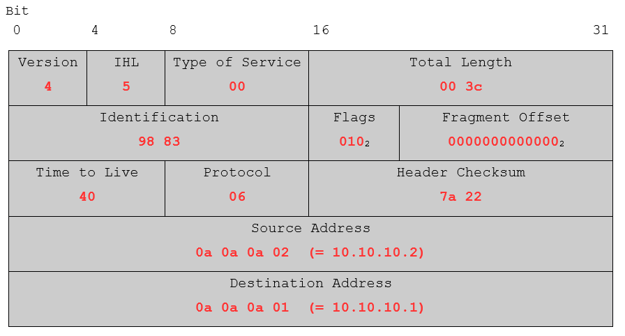
For better readability, the flags and the fragment offset have been converted from hex to binary. Overall, the values seem to be correct. Just to name a few: IP Version 4 was used, the IP header length (IHL) is in fact 5 (5 * 32 bits), the time to live of the packet is set to 40 (64 in decimal) which is a typical value for *nix systems and the source and destination addresses do also look right.
TCP segment
Now that we had a look at the IP part of the packet, let’s look at the TCP segment:
Utilizing our previous acquired knowledge about TCP we insert the values in our packet blueprint:
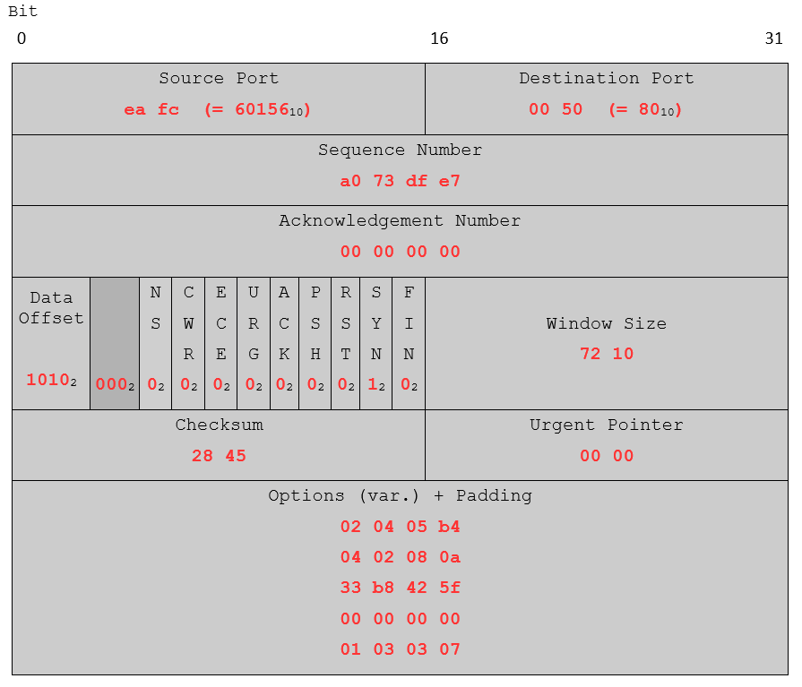
Again, for the data offset, the reserved space and the flags, the hex values were converted to binary. Judging from the source and destination port, the data offset 1010 (10 in decimal, 10 * 32 bits) and the set SYN flag, this packet looks alright. You may try this approach with other TCP/IP packets you captured with Wireshark. Either take one from your own Wireshark dump or use these exercise packets. Use the IHL to separate the IP and TCP segments. What kind of packets can you identify?
That’s it for the analysis of the packets. In the next part, we will create a packet from the scratch by ourselves, put it on the wire and send it.