Recap on network layers and protocols
In this chapter we are going to have a look at the foundational basics of communication protocols used in networks like the internet. The knowledge we gain here will later be used to manually create network packets and send them to other hosts on our network. In case you are very familiar with the TCP/IP network layer, protocols and three-way handshake you can skip this first part and dive directly into the analysis of raw TCP/IP packets.
Networking models
For the communication between two hosts in the internet, a layered networking model is used. There exists a vast amount of networking models and depending on where you came into contact with them first, you might know one or more of them with different numbers of vertical layers. The number of vertical layers range from anywhere between three (Arpanet Reference Model) and seven (OSI model).
For this series we are going to use the five layered model from Andrew Tanenbaum:
| 5 | Application |
| 4 | Transport |
| 3 | Internet |
| 2 | Data link |
| 1 | Physical |
When data is transmitted from one host to another, the data is handed downwards from the uppermost layer to the bottom layer of the sending host. At each level, the current layer adds its own header (or trailer) and hands it further downwards. This process is also called encapsulation.
At the bottom layer the data is transmitted to the receiving host, which then does the same process in reverse. Handing the received transmission from the bottom to the top with each layer removing their header (or trailer).
For our use cases in this series, the layers 3 (Internet) and 4 (Transport) will be the most relevant ones. Therefore, we will have a look at two of the most prominent protocols in these layers.
Internet Protocol (IP)
The Internet Protocol (IP) is the principal communication protocol for the internet as we know it today. Its purpose is delivering packets from the source host to the destination host based on the IP addresses in the packet headers. It is a connectionless protocol meaning that errors such as data corruption, packet loss or duplication might occur. Packets of connectionless protocols are also called datagrams. The Internet Protocol exists in two versions, IP Version 4 (IPv4) and IP Version 6 (IPv6).
The following table shows the basic format of an IPv4 header:
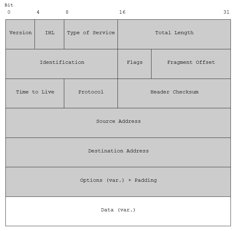
Indicates the protocol version, e.g. IPv4 or IPv6
The IP Header Length is the length of the header in 32 bit words. The minimum value is 5 words (in case no options are set), the maximum 15. Therefore, the maximum header length is 60 bytes [32bit * 15 = 480bit == 60 bytes], the minimal length is 20 bytes.
Also known as Differentiated Services, it is used for quality of service. The first 6 bit are the Differentiated Services Code Point (DSCP), the last 2 bits are the Explicit Congestion Notification (ECN) used to notify the receiver in case of network congestion.
Indicates the total length of the packet in bytes. The maximum length of a packet is 65 535 Bytes.
All fragments of a packet have the same identification number, aiding the receiver to assemble fragmented packets.
The first bit is unused. The two other bits are the DF (Don’t Fragment) and the MF (More Fragments) bits. The DF indicates to router to not fragment the packet. The MF flag signals, that more fragments are about to come. All fragments, except the last one, have this bit set, indicating that the last fragment was received.
This field indicates where in the packet this fragment belongs. Together with the values of Identification and MF this ensures the reassembling of fragmented packets.
This field is a counter which limits the lifetime of a packet and is decreased by every router on the packet’s way. When it hits zero, the router will discard the packet and send a ICMP error message to the sender.
This field indicates the next level protocol used in the data portion of the packet. For example TCP would be value 6, UDP value 17.
A checksum on the header only. Since some header fields change (e.g., time to live), this is recomputed and verified at each point (e.g. router) that the internet header is processed.
The source IP address.
The destination IP address.
The options field is optional and seldomly used. In case it is used, it’s value must be padded with zeros to a multiple of 32 bits because of the IHL.
This field contains the payload of the packet. The data is not part of the header, and therefore not included in the Header Checksum.
Transmission Control Protocol (TCP)
Together with the internet layer, the transport layer is responsible for many internet applications like the World Wide Web. The transport layer provides applications a logical host-to-host connectivity hiding complexity from applications by presenting them an abstraction of the network connection, e.g. through a network socket. The Transmission Control Protocol (TCP) we are going to look at here is a reliable, ordered and error-checked protocol. It provides mechanisms for connection establishment/termination, reliable transmission, error detection, flow/congestion control, and more. In contrast to that, the User Datagram Protocol (UDP), another popular transport layer protocol, is connectionless and unreliable, however, faster than TCP.
The following table shows the basic format of a TCP header (used together with IPv4):
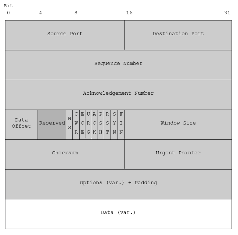
The number or the source port. 0-1023 are ‘well known ports’, 1024-49151 are ‘registered ports’, 49152-65535 are ‘dynamic ports’
The receiving port number.
The sequence number is the first data byte in this segment. In case the SYN flag is set, the sequence number is the initial sequence number (ISN) and the first data byte is ISN+1.
If the ACK flag is set, this field contains the value of the next sequence number the sender of the segment is expecting to receive.
Indicates the size of the TCP header in 32-bit words. The minimum value is 5 words, the maximum 15. Therefore, the maximum header length is 60 bytes [32bit * 15 = 480bit == 60 bytes], the minimal length is 20 bytes. The field is also the offset from the start of the TCP segment to the actual data.
Reserved for future usage, must be set to 0.
| NS | experimental: ECN – concealment protection |
| CWR | Congestion Window Reduced; used for the congestion control mechanism |
| ECE | ECN-Echo; used for the congestion control mechanism |
| URG | Indicates that the Urgent Pointer field is significant |
| ACK | Indicates that the Acknowledgement field is significant |
| PSH | Asks to push the buffered data to the receiving application and not wait for the buffer to be filled |
| RST | Reset the connection |
| SYN | Synchronize sequence numbers |
| FIN | No more data from sender |
Used for flow control and window scaling. Allowing the sender to signalize the number of window size units he is currently willing to receive.
This field is for error detection. Therefore, header, payload and a pseudo-header (consisting out of: Source IP address, Destination IP address, protocol number and total length of the packet) are used.
If the URG flag is set, the urgent pointer points to the sequence number of the byte following the urgent data.
The options field is optional and can be used for example for signaling maximum segment size, timestamps and more. In case it is used, it’s value must be padded with zeros to a multiple of 32 bits.
This field contains the payload of the packet. The data is not part of the header.
Connection Establishment
TCP uses a three-way handshake in order to establish a connection. Let’s assume that host A wants to connect to host B:
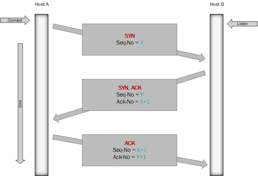
- SYN: Host A send a
[SYN]to host B with a random value as sequence number X. - SYN-ACK: Host B replies on this connection attempt by sending a
[SYN ACK]. The sequence number Y is randomly chosen by host B. The acknowledgement number is the received sequence number increased by one i.e. X+1. - ACK: Host A send an
[ACK]to host B. The sequence number is the previously received acknowledgement number X+1. The new acknowledgement number is the received sequence number increased by one i.e. Y+1.
At this point, the connection between the hosts is established as both of them received an acknowledgement of the connection.